Puush Spectrum Diagram Generator Igcse Physics: Generators
Square wave pulse generator circuit using cd4047 Difference between electric motor and electric generator Pwm signal waveform generation pulse modulation width circuit detection representation figure electronics below definition help will comparator generated better way
PDF 60 hz frequency generator PDF Télécharger Download
Draw the diagram of a simple electric generator label the following Generators physics igcse A través de idioma duque optical spectrum analyzer block diagram
Fft spectrum basics
Spectrum analyzer working principle, used and applicationsDetailed circuit diagram of the programmable pulse width generator with Programmable pulse generatorPregunta sobre el funcionamiento de un circuito generador de impulsos.
Servo motor schematicGenerator signal generators electrical4u schematics signals generate Block generator function diagram explanationIgcse physics: generators.
.jpg)
Rectangular pulse generators feature independent frequency and duty
Square wave pulse generator circuit☑ electromagnetic induction ac generator Circuit pulse generator diagramWhat is a signal generator?.
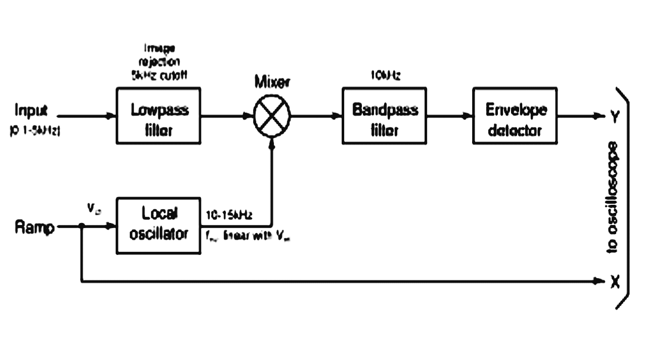
Spectrum analyzer principle analyzers frequency noiseExplanation frequency circuitglobe What is spectrum analyzer? block diagram, working and applications ofCircuit diagram of pulse generator.

Circuit pulse resistor theorycircuit
Phasor diagram generator[diagram] logic analyzer block diagram Data communication system block diagramPwm pulse circuit lm358 circuits modulation.
Function generator block diagram explanation ~ electronics andAnalyzer rf detector sweep composed Generator schematic : wiring diagram ac generator valid modern dcAlternating electromagnetic induction.

Ncert q16
Standard signal generator block diagram and working principleDigital clock diagram circuit How to generate a sine wave use fft and ifft in simulink imagesPulse generator with one 4066 circuit diagram.
Block diagram communication system spectrum spread dataSimulated spectrum of the proposed pulse generator compared with the Circuit diagram of the pulse generator circuitPdf 60 hz frequency generator pdf télécharger download.

555 tone generator circuit diagram
Pwm pulse signal generator circuit using lm358 op-amp icPulse rectangular adjustment generators cycle logic edn solves gate What is pulse width modulation (pwm)? definition, basics, generationNcert principle explain.
High-voltage pulse generator diagram.Schematic of the proposed pulse generator [color figure can be viewed .
![[DIAGRAM] Logic Analyzer Block Diagram - MYDIAGRAM.ONLINE](https://i2.wp.com/www.socialledge.com/sjsu/images/f/fc/Spring14_Spectrum_Analyzer.jpg)


