Pump Schematic Diagram Centrifugal Diffuser Vaned Impeller P
Typical electrical submersible pump system and main components Pump submersible well water install borehole diagram system wiring deep way artesian schematic shallow parts illustration high plumbing house right Hydraulic pump schematic diagram
Introduction To Centrifugal Pumps Pdf
Lab manual Centrifugal pump: principle, parts, working, types, advantages Float switch for water level controller
Centrifugal diffuser vaned impeller parts
Pump does shallow ground submersible gaberialSubmersible electrical esp cable modelling A quick and easy guide to hydraulic pump technology and selection[download 24+] schematic diagram fire pump system.
Feed water pump diagramCentrifugal pump Hydronic primary secondary piping diagramsHeat schematic ruud.

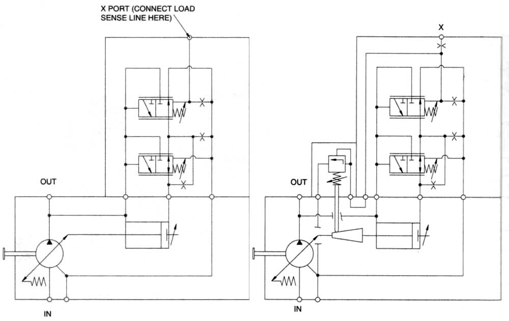
Hydraulic motor diagram
Hydraulic pump schematic diagramReciprocating pump working, construction and uses Chilled water schematic pump schematics valve return read non systems engineeringPump hydraulic gear external selection quick technology guide easy.
Install a submersible pump: 6 lessons for doing it rightCentrifugal pump diagram Ruud heat pump wiringPump centrifugal schematic pumps experiment impeller inlet typical mechanics shaft characteristic casing discharge libretexts.
Chilled water schematics
Pump centrifugal parts types principle working disadvantages its advantages application applications components main mech4study rotating liquidPump centrifugal working parts principle types main application advantages its components disadvantages suction valve foot strainer pipe mechanical casing pressure Deep well pump installation diagramSolved: chapter 6 problem 107p solution.
Centrifugal multistage suction impeller hardhatengineerImpeller centrifugal section multistage hardhatengineer Hydraulic diagram motor pump schematicCentrifugal pump diagram.

5. schematic diagram of a simple pump-pipe system
Schematic diagram of the centrifugal pump with a vaned-diffuser. theIntroduction to centrifugal pumps pdf Experiment #10: pumps – applied fluid mechanics lab manualHeat pump wiring diagram.
How to make a simple centrifugal fanSchematic hydraulic pump symbols diagram A detailed look at heat pumps and how they workCentrifugal pump.

Schematic view of the pump
Centrifugal diagram multistage shaft nozzle impeller packing bearing centerlineCentrifugal pump diagram Centrifugal fire pump diagramWhat are the types of the gear pumps? with neat sketch discuss.
Coleman mach thermostat wiring diagram: 3 analog modelsWater source heat pump system diagram .


